PRODUCTS

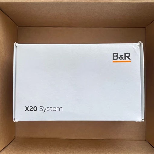
B&R X20CP1382 X20 PLC CPU Module

Product description:

Model: X20CP1382
Brand: B&R
Type: X20 Series Compact PLC CPU with Integrated I/O (1 Slot)
Description:
Intel x86 400 MHz compatible with integrated I/O processor
Ethernet, POWERLINK with poll-response chaining and onboard USB
1 slot for modular interface expansion
30 digital inputs/outputs and 2 analog inputs integrated in the device
2 GB onboard flash drive
256 MB DDR3 SDRAM
Fanless
No battery
Backed-up real-time clock
Warranty: 100% New Original
Shipping: Fast Global Shipping via FedEx and DHL Express

Product introduction

Short description
Interfaces1x RS232, 1x Ethernet, 1x POWERLINK, 2x USB, 1x X2X Link, 1x CAN bus
System moduleController
General information
B&R ID code0xDABB
CoolingFanless
Status indicatorsCPU function, Ethernet, POWERLINK, RS232, CAN bus, CAN bus terminating resistor, PLC power supply, I/O power supply, I/O function per channel
Diagnostics
OutputsDigital outputs: Yes, using LED status indicator and software (output error status)
CPU functionYes, using LED status indicator
CAN bus data transferYes, using LED status indicator
RS232 data transferYes, using LED status indicator
InputsAnalog inputs: Yes, using LED status indicator and software
EthernetYes, using LED status indicator
I/O power supplyYes, using LED status indicator
POWERLINKYes, using LED status indicator
Supply voltage monitoringYes, using LED status indicator
TemperatureYes, using software register
Terminating resistorYes, using LED status indicator
Support
Controller redundancyNo
ACOPOS supportYes
reACTION-capable I/O channelsNo
Visual Components supportYes
Power consumption without interface module and USB5.5 W
Power consumption for X2X Link power supply 0.8 W
Power consumption
Internal I/O2.3 W
Additional power dissipation caused by actuators (resistive) [W]-
Type of signal linesShielded lines must be used for all high-speed digital inputs/outputs, line length: Max. 20 m
Certifications
CEYes
UKCAYes
CRA (Cyber Resilience Act)Evaluation ongoing
ATEXZone 2, II 3G Ex nA nC IIA T5 Gc
IP20, Ta (see X20 user's manual)
FTZÚ 09 ATEX 0083X
ULcULus E115267
Industrial control equipment
HazLoccCSAus 244665
Process control equipment
for hazardous locations
Class I, Division 2, Groups ABCD, T5
DNVTemperature: B(0 to 55°C)
Humidity: B(up to 100%)
Vibration: B(4 g)
EMC: B(bridge and open deck)
CCSYes
LRENV1
KRYes
ABSYes
BVEC33B
Temperature: 5 - 55°C
Vibration: 4 g
EMC: Bridge and open deck
CPU and X2X Link power supply
Input voltage24 VDC -15% / +20%
Input currentMax. 1 A
FuseIntegrated, cannot be replaced
Reverse polarity protectionYes
X2X Link power supply output
Nominal output power2 W
Parallel connectionYes
Redundant operationYes
Input I/O power supply
Input voltage24 VDC -15% / +20%
FuseRequired line fuse: Max. 10 A, slow-blow
Output I/O power supply
Nominal output voltage24 VDC
Permissible contact load10 A
Controller
Real-time clockRetention for at least 300 hours, typ. 1000 hours at 25°C, 1 s resolution, -18 to 28 ppm accuracy at 25°C
FPUYes
Processor
TypeVx86EX
Clock frequency400 MHz
L1 cache
Data code16 kB
Program code16 kB
L2 cache128 kB
Integrated I/O processorProcesses I/O data points in the background
Modular interface slots1
Remanent variables32 kB FRAM, retention >10 years
Shortest task class cycle time1 ms
Typical instruction cycle time0.0199 µs
Standard memory
RAM256 MB DDR3 SDRAM
Application memory
Type2 GB eMMC flash memory
Data retention10 years
Writable data amount
Guaranteed40 TB
Results for 5 years21.9 GB/day
Guaranteed erase/write cycles20,000
Error-correcting code (ECC)Yes
Interfaces
Interface IF1
SignalRS232
VariantConnection via 16-pin terminal block X20TB1F
Max. distance900 m
Transfer rateMax. 115.2 kbit/s
Interface IF2
SignalEthernet
Variant1x RJ45 shielded
Line lengthMax. 100 m between 2 stations (segment length)
Transfer rate10/100 Mbit/s
Transfer
Physical layer10BASE-T/100BASE-TX
Half-duplexYes
Full-duplexYes
AutonegotiationYes
Auto-MDI/MDIXYes
Interface IF3
FieldbusPOWERLINK managing or controlled node
TypeType 4
Variant1x RJ45 shielded
Line lengthMax. 100 m between 2 stations (segment length)
Transfer rate100 Mbit/s
Transfer
Physical layer100BASE-TX
Half-duplexYes
Full-duplexPOWERLINK mode: No / Ethernet mode: Yes
AutonegotiationYes
Auto-MDI/MDIXYes
Interface IF4
TypeUSB 1.1/2.0
VariantType A
Max. output current0.5 A
Interface IF5
TypeUSB 1.1/2.0
VariantType A
Max. output current0.1 A
Interface IF6
FieldbusX2X Link master
Interface IF7
SignalCAN bus
VariantConnection via 16-pin terminal block X20TB1F
Max. distance1000 m
Transfer rateMax. 1 Mbit/s
Terminating resistorIntegrated in module
ControllerSJA 1000
Digital inputs
Quantity14 standard inputs, 4 high-speed inputs and 4 mixed channels, configuration as input or output using software
Nominal voltage24 VDC
Input voltage24 VDC -15% / +20%
Input current at 24 VDCX1 - Standard inputs: Typ. 3.5 mA
X2 - Standard inputs: Typ. 2.68 mA
X2 - High-speed inputs: Typ. 3.5 mA
X3 - Mixed channels: Typ. 2.68 mA
Input circuitSink
Input filter
HardwareStandard inputs and mixed channels: ≤200 μs
High-speed inputs: ≤2 μs, when used as standard inputs: ≤200 μs
SoftwareDefault 1 ms, configurable between 0 and 25 ms in 0.1 ms increments
Connection type1-wire connections
Input resistanceX1 - Standard inputs: 6.8 kΩ
X2 - Standard inputs: 8.9 kΩ
X2 - High-speed inputs: 6.8 kΩ
X3 - Mixed channels: 8.9 kΩ
Additional functionsX2 - High-speed digital inputs:
2x 250 kHz event counting, 2x AB counter, ABR incremental encoder, direction/frequency, period measurement, gate measurement, differential time measurement, edge counters, edge times
Switching threshold
Low<5 VDC
High>15 VDC
AB incremental encoder
Quantity2
Encoder inputs24 V, asymmetrical
Counter size32-bit
Input frequencyMax. 100 kHz
Evaluation4x
Encoder power supplyModule-internal, max. 300 mA
Overload characteristics of encoder power supplyShort-circuit proof, overload-proof
ABR incremental encoder
Quantity1
Encoder inputs24 V, asymmetrical
Counter size32-bit
Input frequencyMax. 100 kHz
Evaluation4x
Encoder power supplyModule-internal, max. 300 mA
Overload characteristics of encoder power supplyShort-circuit proof, overload-proof
Event counters
Quantity2
Signal formSquare wave pulse
Evaluation1x
Input frequencyMax. 250 kHz
Counter frequency250 kHz
Counter size32-bit
Edge detection / Time measurement
Possible measurementsPeriod measurement, gate measurement, differential time measurement, edge counter, edge times
Measurements per moduleEach function up to 2x
Signal formSquare wave pulse
Counter size32-bit
Input frequencyMax. 10 kHz
Timestamp1 µs resolution
Analog inputs
Input±10 V or 0 to 20 mA / 4 to 20 mA, via different terminal connections
Input typeDifferential input
Digital converter resolution
Voltage±12-bit
Current12-bit
Conversion time1 channel enabled: 100 µs
2 channels enabled: 200 µs
Output format
Data typeINT
VoltageINT 0x8001 - 0x7FFF / 1 LSB = 0x0008 = 2.441 mV
CurrentINT 0x0000 - 0x7FFF / 1 LSB = 0x0008 = 4.883 μA
Input impedance in signal range
Voltage20 MΩ
Current-
Load
Voltage-
Current<300 Ω
Input protectionProtection against wiring with supply voltage
Permissible input signal
VoltageMax. ±30 V
CurrentMax. ±50 mA
Output of digital value during overloadConfigurable
Conversion procedureSAR
Input filterThird-order low-pass filter / Cutoff frequency 1 kHz
Max. error
Voltage
Gain0.18% (Rev. <C0: 0.37%)
Offset0.04% (Rev. <C0: 0.25%)
Current
Gain0 to 20 mA = 0.15% (Rev. <C0: 0.52%) / 4 to 20 mA = 0.25%
Offset0 to 20 mA = 0.1% (Rev. <C0: 0.4%) / 4 to 20 mA = 0.15%
Max. gain drift
Voltage0.017 %/°C
Current0 to 20 mA = 0.015 %/°C / 4 to 20 mA = 0.023 %/°C
Max. offset drift
Voltage0.008 %/°C
Current0 to 20 mA = 0.008 %/°C / 4 to 20 mA = 0.012 %/°C
Common-mode rejection
DC70 dB
50 Hz70 dB
Common-mode range±12 V
Crosstalk between channels<-70 dB
Nonlinearity
Voltage<0.025%
Current<0.05%
Resistance measurement temperature inputs
Quantity1
InputResistance measurement with constant current supply for 2-wire connections
Digital converter resolution13-bit
Conversion timeOnly temperature input enabled: 200 µs
Temperature and analog input enabled: 400 µs
Conversion procedureSAR
Output formatINT or UINT for resistance measurement
Sensor
Pt1000-200 to 850°C
Resistance measurement range0.1 to 4000 Ω
Temperature sensor resolution1 LSB = 0x0005 = 0.16°C
Resistance measurement resolution1 LSB = 0x0005 = 0.49 Ω
Input filterFirst-order low-pass filter / cutoff frequency 7 Hz
Sensor standardEN 60751
Common-mode range1 V
Linearization methodInternal
Measuring current1 mA
Permissible input signalShort-term max. ±30 V
Max. error at 25°C
Gain0.3% (Rev. <C0: 1.93%)
Offset0.15% (Rev. <C0: 0.32%)
Max. gain drift0.023 %/°C
Max. offset drift0.012%/°C
Nonlinearity<0.05%
Standardized range of values for resistance measurement0.1 to 4000.0 Ω
Crosstalk between channels<-70 dB
Common-mode rejection
50 Hz>60 dB
Temperature sensor normalization
Pt1000-200 to 850°C
Digital outputs
Quantity4 standard outputs, 4 high-speed outputs and 4 mixed channels, configuration as input or output using software
VariantStandard outputs and mixed channels: Current-sourcing FET
High-speed outputs: Push-Pull
Nominal voltage24 VDC
Switching voltage24 VDC -15% / +20%
Nominal output currentStandard outputs and mixed channels: 0.5 A
High-speed outputs: 0.2 A
Total nominal currentStandard outputs and mixed channels: 4 A
High-speed outputs: 0.8 A
Connection type1-wire connections
Output circuitStandard outputs and mixed channels: Source
High-speed outputs: Sink or source
Output protection Thermal shutdown in the event of overcurrent or short circuit (see value "Short-circuit peak current")
Internal freewheeling diode for switching inductive loads (see section "Switching inductive loads")
Pulse width modulation
Period duration5 to 65535 µs corresponds to 200 kHz to 15 Hz
Pulse duration0 to 100%, minimum 2.5 µs
Resolution for pulse duration0.1% of the configured frequency
Diagnostic statusStandard outputs and mixed channels: Output monitoring with 10 ms delay
High-speed outputs: Output monitoring with 10 µs delay
Leakage current when the output is switched offStandard outputs and mixed channels: 5 µA
High-speed outputs: 25 µA
RDS(on)140 mΩ
Residual voltageStandard outputs and mixed channels: <0.1 V at nominal current 0.5 A
High-speed outputs: <0.9 V at nominal current 0.1 A
Peak short-circuit currentStandard outputs and mixed channels: <3 A
High-speed outputs: <20 A
Switch-on in the event of overload shutdown or short-circuit shutdownStandard outputs and mixed channels: Approx. 10 ms (depends on module temperature)
High-speed outputs: No switch-on
Switching delay
0 → 1Standard outputs and mixed channels: <300 µs
High-speed outputs: <3 µs
1 → 0Standard outputs and mixed channels: <300 µs
High-speed outputs: <3 µs
Switching frequency
Resistive load Standard outputs and mixed channels: Max. 500 Hz
High-speed outputs: 50 kHz, max. 200 kHz (see section "Switching frequency derating for high-speed digital outputs")
Inductive loadSee section "Switching inductive loads".
Braking voltage when switching off inductive loadsStandard outputs and mixed channels: Typ. 45 VDC
Electrical properties
Electrical isolationEthernet (IF2), POWERLINK (IF3) and X2X (IF6) isolated from each other, from other interfaces and from PLC
Channel isolated from bus
Channel not isolated from channel or PLC
Operating conditions
Mounting orientation
HorizontalYes
VerticalYes
Installation elevation above sea level
0 to 2000 mNo limitation
>2000 mReduction of ambient temperature by 0.5°C per 100 m
Degree of protection per EN 60529IP20
Ambient conditions
Temperature
Operation
Horizontal mounting orientation-25 to 60°C
Vertical mounting orientation-25 to 50°C
DeratingSee section "Switching frequency derating for high-speed digital outputs".
Storage-40 to 85°C
Transport-40 to 85°C
Relative humidity
Operation5 to 95%, non-condensing
Storage5 to 95%, non-condensing
Transport5 to 95%, non-condensing
Mechanical properties
NoteX20 end cover plate (right) included in delivery
3 X20 terminal blocks (16-pin) included in delivery
Interface module slot cover included in delivery
Dimensions
Width164 mm
Height99 mm
Depth75 mm
Weight310 g


1

Shipping Method:

2

Leave a message

Submit

相关推荐